|
Product Details:
|
Surface: | Varnished Transparent Oil, Rust-proof Oil, Hot Galvanizing | Standard: | ASME,AISI, DIN, JIS |
---|---|---|---|
Pressure: | 150# - 2500# | Size: | 1/2"-24" |
Port: | Tianjin | ||
Highlight: | 24 Inch Flange Long Welding Neck,600 LBS Flange Long Welding Neck,24 Inch Straight Hub Welding Flanges |
Specifications of ASME B16.5 A105 1/2" - 24" 150# RF Weld Neck Flange
Weld Neck Flange Standards | ANSI/ASME B16.5, B16.47 Series A & B, B16.48, BS4504, BS 10, EN-1092, DIN, ANSI Flanges, ASME Flanges, BS Flanges, DIN Flanges, EN Flanges, GOST Flange, ASME/ANSI B16.5/16.36/16.47A/16.47B, MSS S44, ISO70051, JISB2220, BS1560-3.1 |
Weld Neck Flange Size | 1/2″ -- 48″ |
Weld Neck Flange Coating | Oil Black Paint, Anti-rust Paint, Zinc Plated, Yellow Transparent, Cold and Hot Dip Galvanized |
Test | Direct-reading Spectrograph, Hydrostatic testing machine, X-ray detector, UI trasonic flaw detector, Magnetic particle detector |
Weld Neck Flange Pressure |
Class 150 LBS, 300 LBS, 600 LBS, 900 LBS, 1500 LBS, 2500 LBS |
Types of Weld Neck Flange |
Forged / Threaded / Screwed / Plate |
Transport Package |
in Wooden Cases or Customers Requirements |
What is Weld Neck Flange
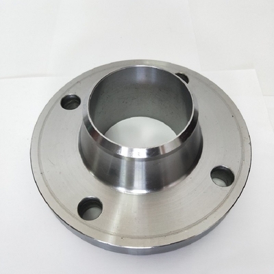
A weld neck flange is a type of flange. There are two designs. The regular type is used with pipes. The long type is unsuitable for pipes and is used in process plant. A weld neck flange consists of a circular fitting with a protruding rim around the circumference. Generally machined from a forging, these flanges are typically butt welded to a pipe. The rim has a series of drilled holes that permit the flange to be affixed to another flange with bolts.
Weld neck flanges are suitable for use in hostile environments that have extremes of temperature, pressure or other sources of stress.The resilience of this type of flange is achieved by sharing the environmental stress with the pipe with which it is welded.This type of flange has been used successfully at pressures up to 5,000 psi.
Dimension of Weld Neck Flange
ze in Inch | Size in mm | Outer Diameter | Flange Thickness | Hub OD | Weld Neck OD | Welding Neck Length | Bore | RF Diameter | RF Height | PCD | Weld Face |
A | B | C | D | E | F | G | H | I | J | ||
1/2 | 15 | 90 | 9.6 | 30 | 21.3 | 46 | Refer Note | 34.9 | 2 | 60.3 | 1.6 |
3/4 | 20 | 100 | 11.2 | 38 | 26.7 | 51 | 42.9 | 2 | 69.9 | 1.6 | |
1 | 25 | 110 | 12.7 | 49 | 33.4 | 54 | 50.8 | 2 | 79.4 | 1.6 | |
1 1/4 | 32 | 115 | 14.3 | 59 | 42.2 | 56 | 63.5 | 2 | 88.9 | 1.6 | |
1 1/2 | 40 | 125 | 15.9 | 65 | 48.3 | 60 | 73 | 2 | 98.4 | 1.6 | |
2 | 50 | 150 | 17.5 | 78 | 60.3 | 62 | 92.1 | 2 | 120.7 | 1.6 | |
2 1/2 | 65 | 180 | 20.7 | 90 | 73 | 68 | 104.8 | 2 | 139.7 | 1.6 | |
3 | 80 | 190 | 22.3 | 108 | 88.9 | 68 | 127 | 2 | 152.4 | 1.6 | |
3 1/2 | 90 | 215 | 22.3 | 122 | 101.6 | 70 | 139.7 | 2 | 177.8 | 1.6 | |
4 | 100 | 230 | 22.3 | 135 | 114.3 | 75 | 157.2 | 2 | 190.5 | 1.6 | |
5 | 125 | 255 | 22.3 | 164 | 141.3 | 87 | 185.7 | 2 | 215.9 | 1.6 | |
6 | 150 | 280 | 23.9 | 192 | 168.3 | 87 | 215.9 | 2 | 241.3 | 1.6 | |
8 | 200 | 345 | 27 | 246 | 219.1 | 100 | 269.9 | 2 | 298.5 | 1.6 | |
10 | 250 | 405 | 28.6 | 305 | 273 | 100 | 323.8 | 2 | 362 | 1.6 | |
12 | 300 | 485 | 30.2 | 365 | 323.8 | 113 | 381 | 2 | 431.8 | 1.6 | |
14 | 350 | 535 | 33.4 | 400 | 355.6 | 125 | 412.8 | 2 | 476.3 | 1.6 | |
16 | 400 | 595 | 35 | 457 | 406.4 | 125 | 469.9 | 2 | 539.8 | 1.6 | |
18 | 450 | 635 | 38.1 | 505 | 457.2 | 138 | 533.4 | 2 | 577.9 | 1.6 | |
20 | 500 | 700 | 41.3 | 559 | 508 | 143 | 584.2 | 2 | 635 | 1.6 | |
24 | 600 | 815 | 46.1 | 663 | 610 | 151 | 692.2 | 2 | 749.3 | 1.6 |
Weld Neck Flange Picture
Features of Weld Neck Flange
Weld Neck Flanges are easy to recognize at the long tapered hub, that goes gradually over to the wall thickness from a pipe or fitting.
The long tapered hub provides an important reinforcement for use in several applications involving high pressure, sub-zero and / or elevated temperatures. The smooth transition from flange thickness to pipe or fitting wall thickness effected by the taper is extremely beneficial, under conditions of repeated bending, caused by line expansion or other variable forces.
These flanges are bored to match the inside diameter of the mating pipe or fitting so there will be no restriction of product flow. This prevents turbulence at the joint and reduces erosion. They also provide excellent stress distribution through the tapered hub and are easily radiographed for flaw detection.
Contact Person: Mr. Janson
Tel: 0086-317-5298199
Fax: 86-317-5295979